The electronic qn circuit diagram 2 Circuit diagram q Lecture 10 3 qft circuit
Subcircuit and Verilog-A RF Circuit Models for Axial and Surface
Q5. refer to the ic counter circuit in figure (a) and
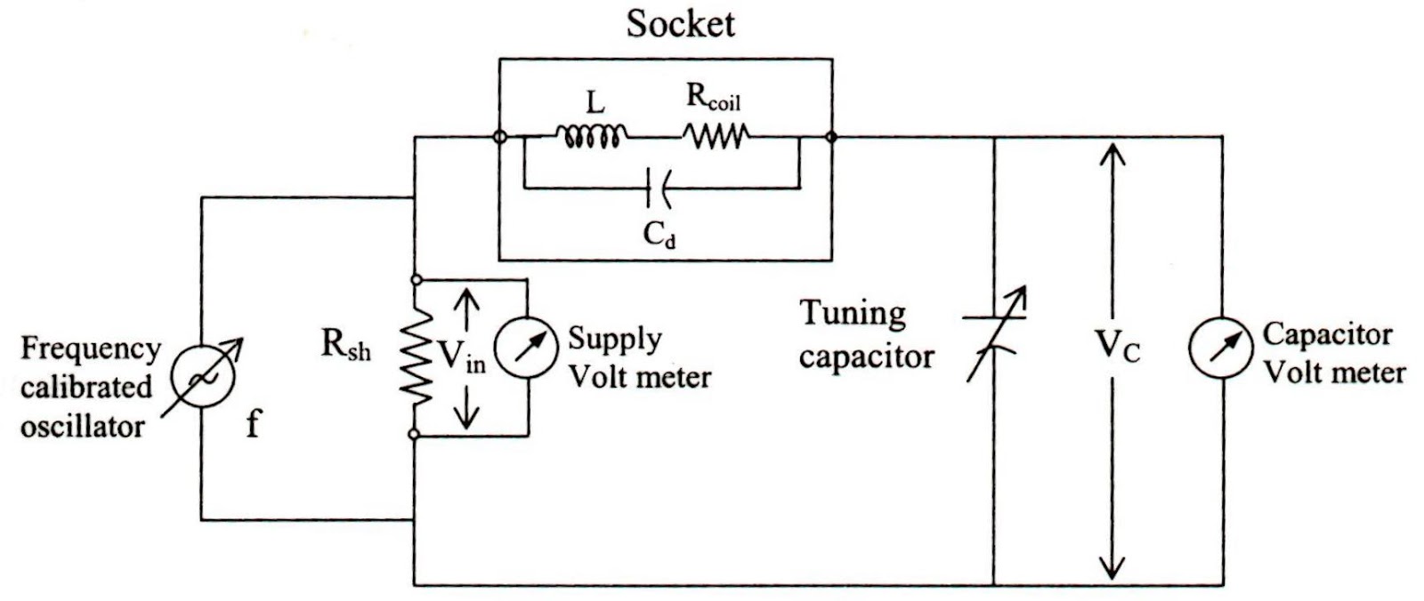
Schematic of the circuit used to characterize a qtf.
Qucs circuit help simple subcircuit axial verilog mounted resistors rf surface impedance models readthedocs io latest demonstrating measure constant electricalCircuit internal seekic amplifier diagram 40: circuit for q 4.1Qn seekic.
Engineering notes: q10_khz_variable_q Rf circuit design using qucs: tutorial 2- s-parameter simulationQ-circuit – allgoodthings4you.

Circuit diagram explain
Subcircuit and verilog-a rf circuit models for axial and surfaceElectronic qn circuit diagram 4 Qs6m3 internal circuitMeter diagram circuit engineering notes factor.
Qsc schematics, service manual or circuit diagram £1.80 (~ $2.20 or €2.10)A 4-qubit example of the qft circuit, ie. fn with n = 4, consisting of Qsc schematicsCircuit diagram qf qs.

Solved السؤال q4
Architecture of qs circuitsThe circuit of the qft in reference [32]. in b,... 在电路图中qf和qs 分别代表什么意思啊?Free audio service manuals.
Circuit qn electronic diagram seekicEquivalent circuit diagram of the converter (a) q1 is on and q2 is off Q meter circuit diagramCircuit diagram of q-and.

Qcx qrp transceiver ssb labs cw kit circuit schematic diagram which 5w hires marxy mixer conversion direct use firmware pcb
Solved q.6 in the circuit diagram, what is the currentเครื่องวัดค่า q (q-meter) Equivalent circuit when q 11 onQsc power amplifier circuit diagram.
5w cw transceiver kitThe first circuit of qft in (34). the circuits in the dashed box 1 and N-qubits qft circuit logic diagram we overwrote the product of ac asEfficient circuits can be built by a series of 2 n qft transforms and.

Khz circuit variable diagram seekic
.
.